| |
The task for the week is to learn how to design a PCB, redraw an echo hello-world board, provided by Fab Academy and to add an additional button and LED, check the design rules, make it, and test it. So to redraw the echo hello-world, I had used Eagle.
Designing
Before Starting, I initiated a list of the required components :
Components list:
:: 1x ATtiny44 microcontroller
:: 1x 1uF Capacitor
:: 1x 10k Ω resistor
:: 1x 499 Ω resistor
:: 1x switch |
:: 1x 20MHz resonator
:: 1x FTDI connector
:: 1x AVRISP smd
:: 1x LED (Red) |
|
|
|
|
|
Here is what the actual board looks like |
|
|
|
| |
|
|
|
| |
|
|
| |
|
|
 |
|
|
| |
|
|
| |
|
|
| |
|
|
| |
Intially, I found it a bit challenging to understand it first,as i have never been into electronics and this was my first time as I do not have any prior experience with PCB design softwares. Step by step I found it interesting and followed the instructions of our instructor's suggestion. He briefed us on how to install libraries, add parts, connect wires and edit schematic layout in Eagle and asked us to tryout any simple design before going into this week’s assignment.
I began this week by downloading Eagle software from Autodesk, for which fab academy provided the licence. Despite having only a little kicad experience.
I decided to use Eagle programme.I also picked it because I want to learn about new and various PCB designing tools.To understand how to install libraries, add parts, connect wires, and alter the schematic layout in Eagle, I first watched a YouTube video.
The tutorial was quite informative, and I quickly became comfortable with the program.
Here are the steps I used to create this week's circuit.
The programs handle Schematic Capture, and PCB Layout with Gerber output (this is what you send to a manufacturere). I started by creating a new project and opened the .sch file in Eeschema. |
|
| |
|
|
| |
PCB Designing : |
|
| |
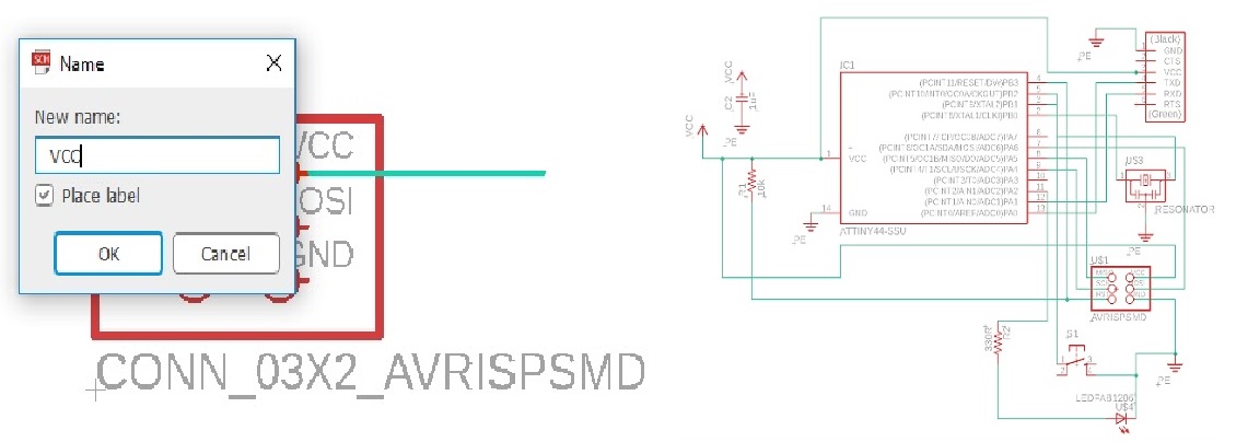
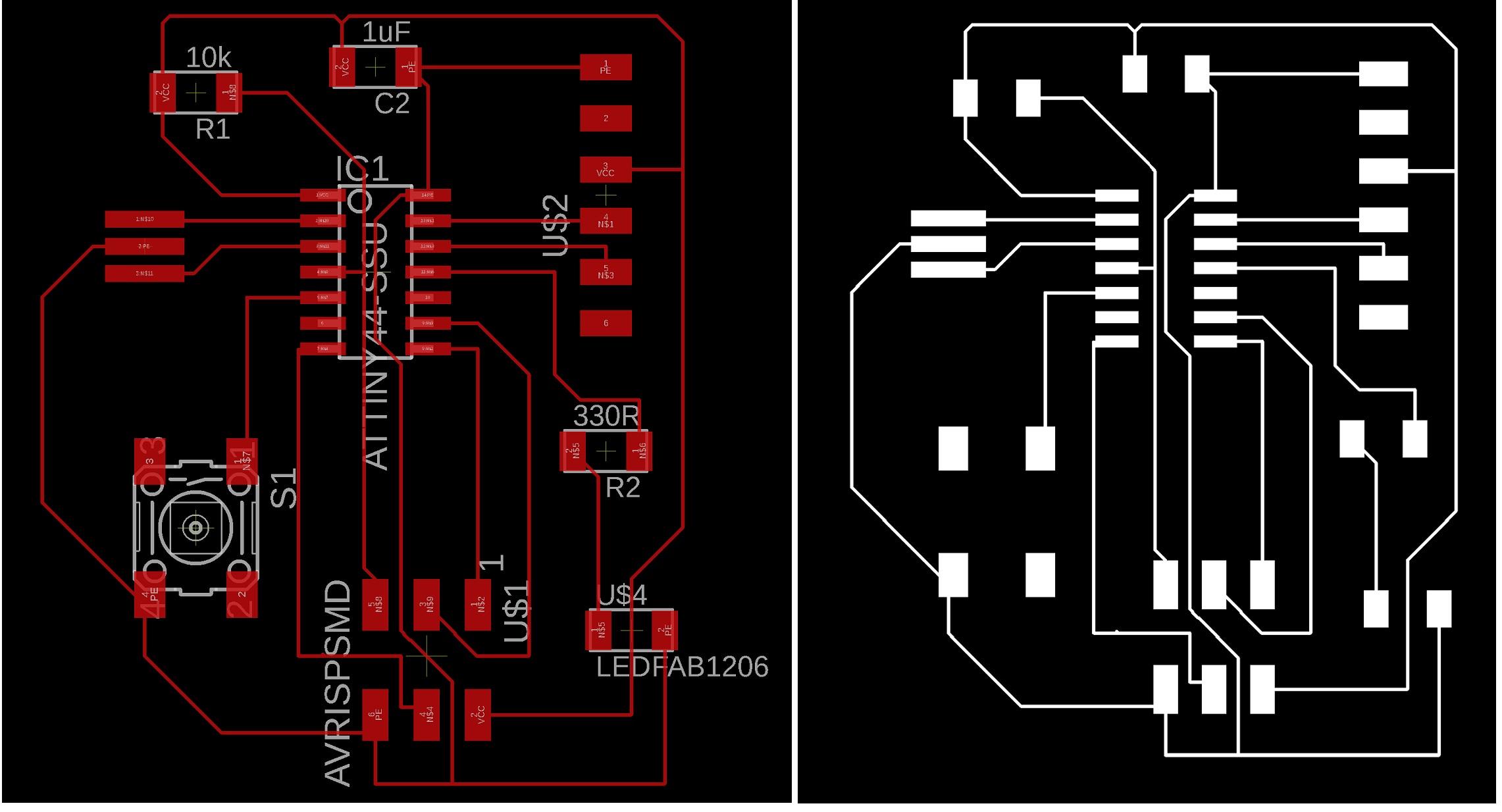
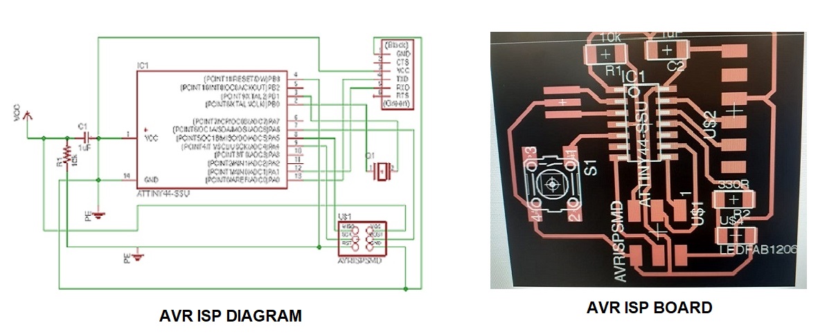
For the design & fabrication of Echo Hello World board, I started with Eagle to create the schematic drawing of the same by follwoing https://academy.cba.mit.edu. I have selected the ATTiny, which is available at our FabLab, ATTINY44-SSU, from fab.ldr and similarly selected all the components. I used the following image to recreate my schematic diagram.
I used the FAB library SMD components. I inserted all the required SMD components for my circuit into the schematic design page.
Then I have added all the required SMD componenets. |
|
| |
|
|
| |
1) VCC
2) GND
3) Resistor
4) Capacitor
5) ATtiny44 |
6) FTDI
7) ISP
8) LED
9) Tactile switch |
|
| |
|
|
| |
|
|
| |
|
|
| |
|
|
|
| |
|
|
|
| |
|
|
|
| |
Since the assignment need to connect an LED and a push button, I updated the schematic diagram accommodating both by which the components can move, rotated and mirrored by clicking on the following icons from the tool bar, then click on the component itself.
Name the pins by typing name in the command line. Change the name to the desired(here VCC) in the popup.
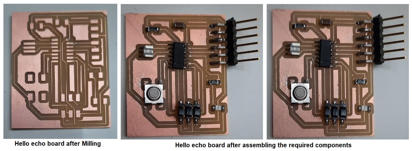
After milling of the board, soldering of the circuit with the help of required component for necessary testing.
|
|
|
| |
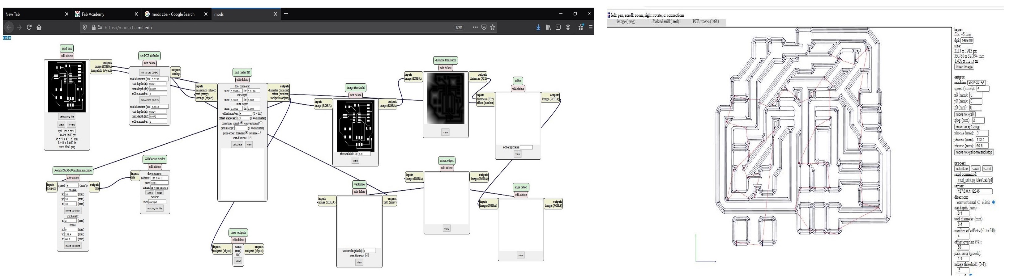
After completion of the board layout, I did the following commands:
- “ratsnest”, to compile the design.
- “display none top”, this will display just the top layer (copper and traces layer).
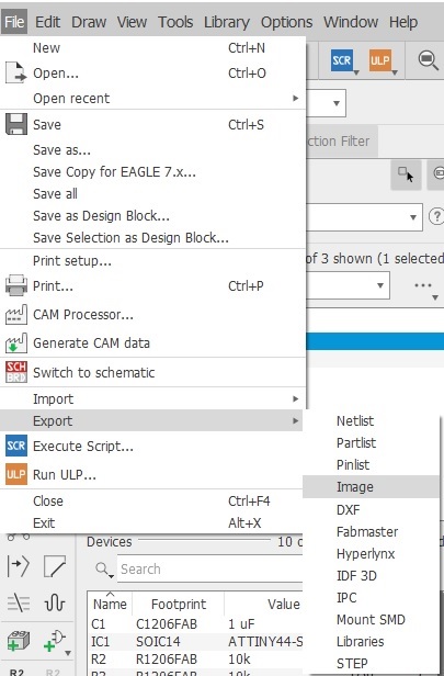
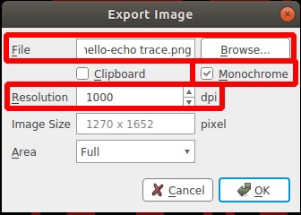
- “export image”, this will enable you to export as .png. Select Monochrome and 1000 dpi.
- “display none dim”. this will display just the dimension layer which is the outline.
- “export image”, same setting but different name (eg. outline.png
|
|
|
| |
Now export the PNG file:: Go to 'FILE' on the MEnu Bar and click 'EXPORT' and select 'IMAGE'. Then a window opens and browse the destination, make it monochrome and change the resolution to 1000dpi.
|
|
|
| |
|
|
| |
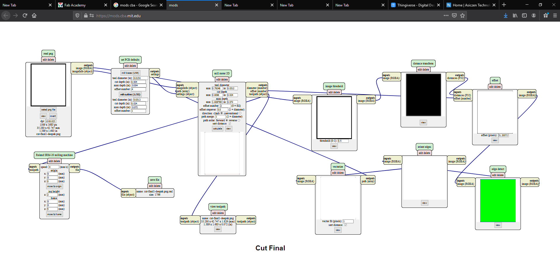
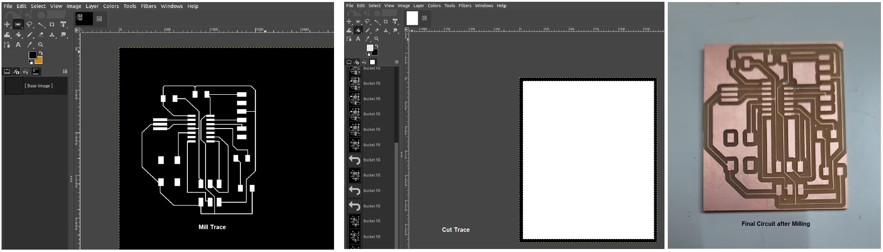
Now exported the file as png as the same way we exported the the traces and after this I created the cut file in the GIMP software after opening the same image in GIMP. |
|
| |
|
|
|
| |
 |
|
| |
|
|
|
| |
Then I mounted & soldered all the required components to the circuit and tested. |
|
|
| |
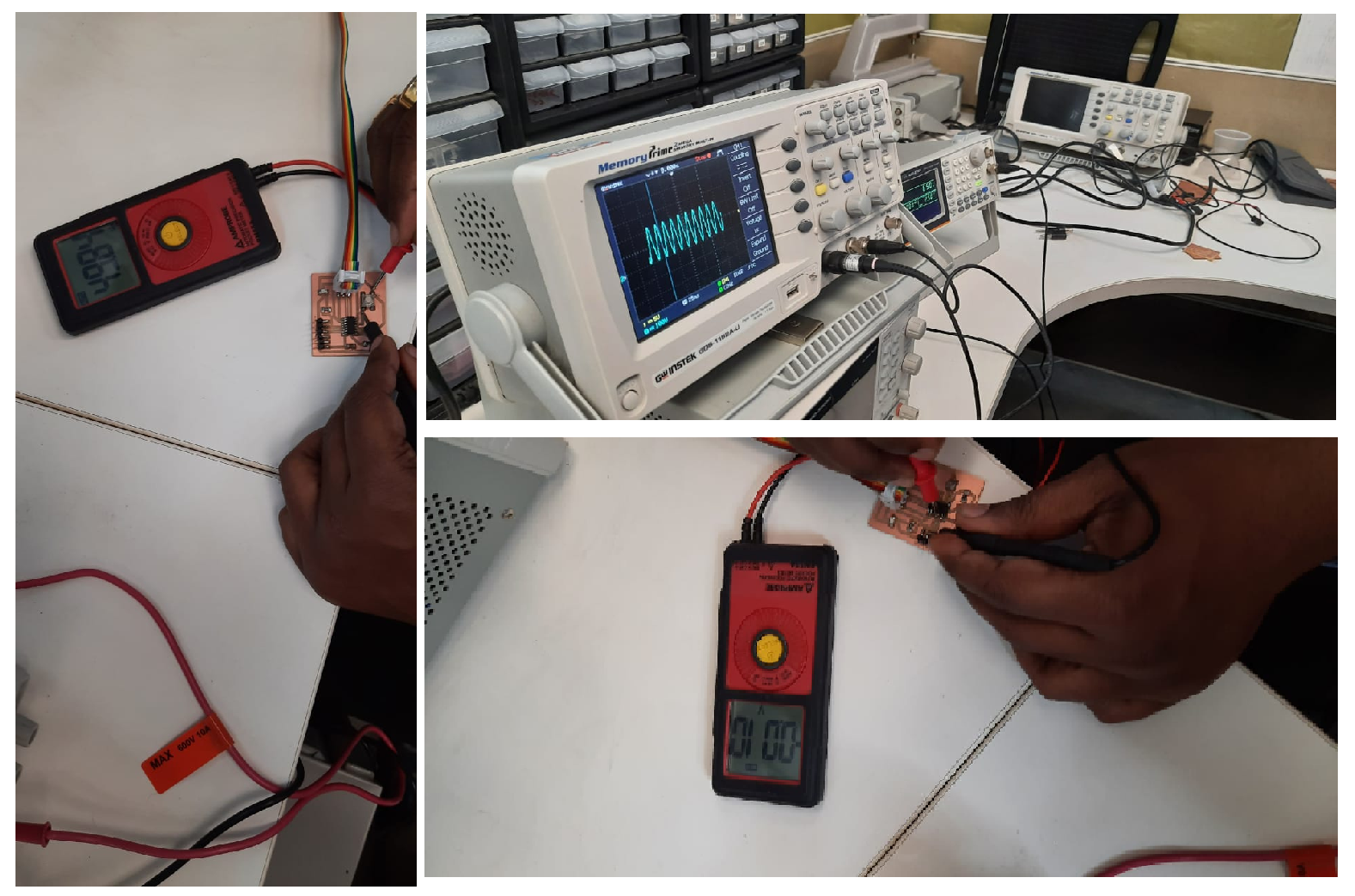
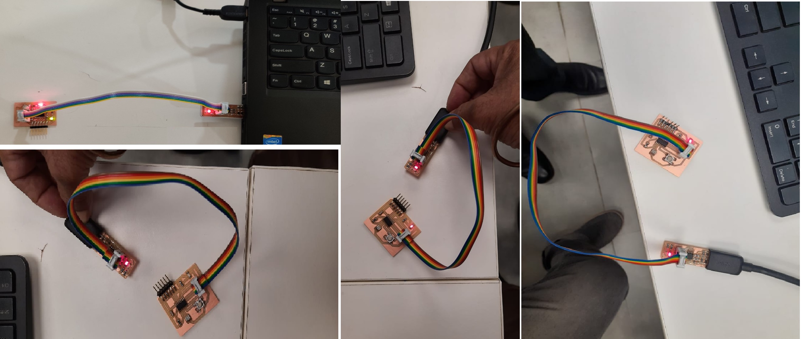
Testing the Board ::
For testing the "Hello Echo board" I connected it to the computer using the "Tiny ISP micro-controller" made during Electronics Production week. Make sure that the ground (GND) of both the boards are connected to each other. |
|
|
| |
|
|
|
| |
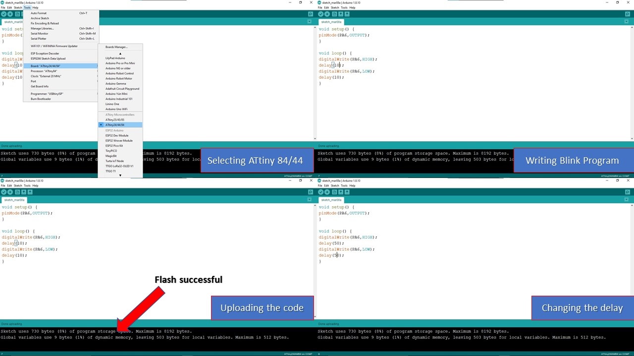
Coding using Arduino IDE
Since, I was not well versed wth the arduino programming i took the help of the instructor Mr.Shibu and with his guidance which I proceeded and helped me in programming the pcb.
First you need to install the Arduino, then you need to select ATTiny 84/44 from Tools section in menu bar. The next step is to write the program, here I had used a simple program that makes the LED blink. Next you need to run and upload the program. |
|
| |
|
|
| |
|
|
|
| |
Final Output |
|
|
| |
After this i programmed the PCB using the FABISP programmer which was made and I connected the FABISPto the hello echo board through the ISP header cable to Check the cable whether it is properly oriented at both the ends and properly connected or not. |
|
| |
|
|
| |
|
|
| |
|
|
| |
|
|
|
| |
|
|
|
| |
|
|
|
| |
|
|
|
| |
|
|
|
| |
|
|
|
| |
|
|
|
| |
|
|
|

